VIBE 2 Assembly Instructions
More photos to be added soon.
Congratulations on purchasing your Vibe 2! It is designed and built with bringing the best performance to you in an easy-to-build airframe.
Note: The following is an assembly manual for a right-handed Vibe 2 with the offset vertical stabilizer, and four servos in the pod installation with torque rods.
Please follow the below assembly guidelines, we have tried to explain each process as clearly as possible through photos and descriptions. In the event that something is unclear, please feel free to send us a message with your questions.
Parts and Materials List
Included Hardware:
Equipment needed to complete the Vibe 2 assembly:
- 1S LiPo battery pack, 300-400 mah, flat cell
- Small full range receiver with end pins, dual antenna is very much preferred (JR RG612BX, JR RG613BX, Graupner GR-16L, etc)
- 4 servos for the fuselage. Stock servo tray is designed for the KST X08 servos. Other thin and small servos will also work, such as the MKS 65K and 75K.
Supplies and equipment needed to assemble the Vibe:
- Model knife (X-acto #11, etc)
- Masking tape
- Pen
- Straightedge
- Thin CA
- CA kicker / accelerator
- 15-minute epoxy
- Microballoons
- Aerosil / Cabosil optional
- Dremel
- Pliers
- Small file (flat and round)
- Phillips screwdriver
- 2mm hex screwdriver
CLICK HERE FOR MY FULL TOOL GUIDE
Wing
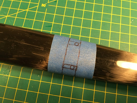
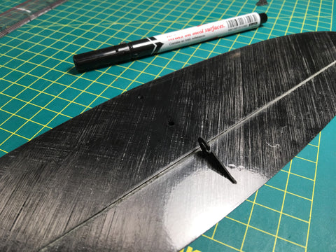
1. Mask the center of the wing on the top surface. With a pen, extend the hingeline until it is 7mm from the centerline of the wing.
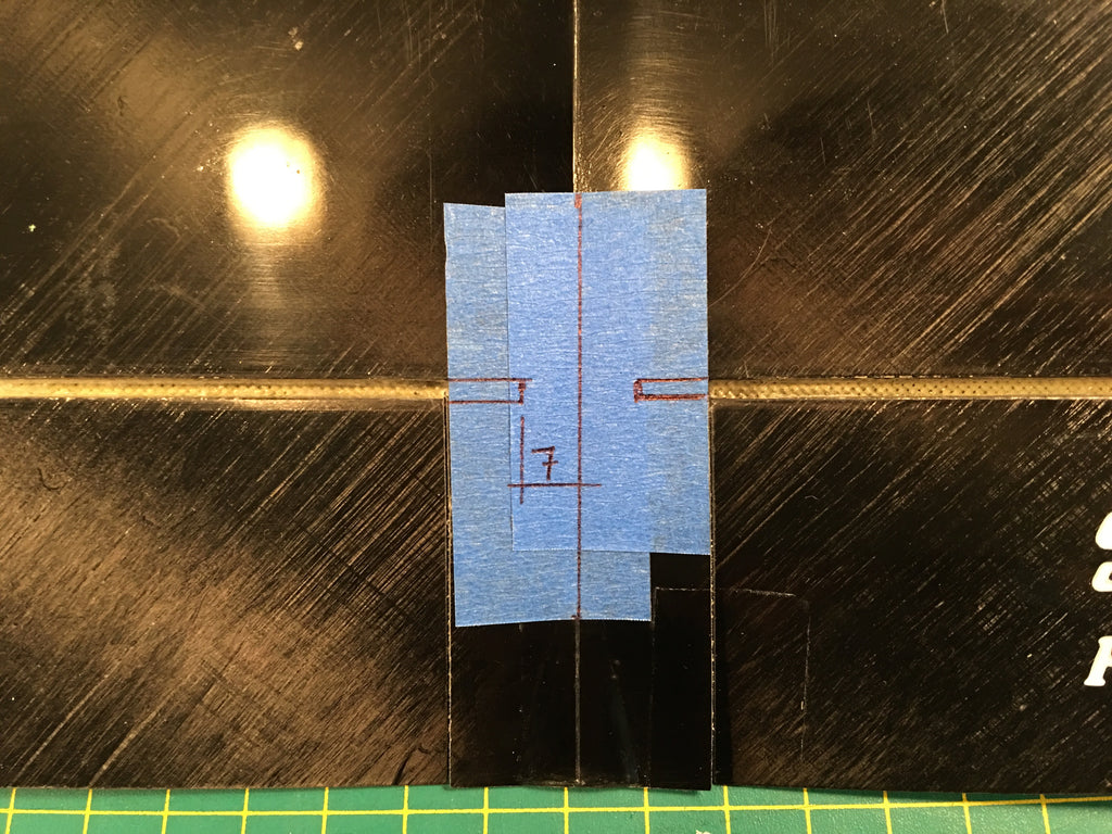
2. Apply masking tape to the top of the flaperons near the root. Overlay the aluminum torque rods on to the top, aligned to the hinge and 7mm mark as pictured below. Mark where the prongs on the torque rod will enter the flaperon.


3. Use a dremel with a drill bit to drill into the center of the wing from the top, extending the hingeline gap. Using a dremel with a drill bit, continue to remove a little bit of material from the forward edge of the hingeline gap (main wing's trailing edge) so that the torque rod can move without restriction. Using a dremel and a drill bit, remove material from the flaperon's leading edge where the torque rods' prongs enter the flaperon. Do not remove material between the two holes for the torque rods - that area is used for aligning your torque rod to the hingeline. At the innermost part of the cut near the root (7mm from the center), drill a hole through the bottom skin. This is where the control horn will pass through the wing and into the fuselage.


4. Test fit the torque pushrods in the flaperons, make sure all movement is unrestricted. You only need about 15mm of upwards deflection for most conditions, some pilots may like more responsive models and use 20mm of upwards deflection. Plug in the control horns to make sure movement is still unrestricted.
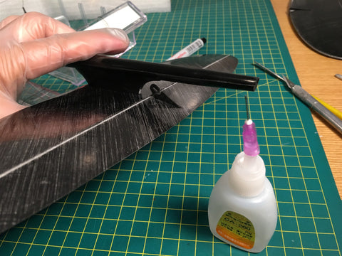
5. *Note: all bonded parts and areas should be scuffed / roughened up, and then cleaned with rubbing alcohol before bonding. Mix some 15-minute epoxy, and thicken with microballoons and some (optional) aerosil. Apply the epoxy mixture into the two holes for the torque rod prongs, and in the leading edge of the flaperon between the two holes. Plug in your torque rods and (IMPORTANT) hold the flaperon against the TOP skin while it cures. If needed, you can do one side at a time to make it easier.
6. Plug in the carbon control horns into the torque rods, make sure the orientation is correct (control horn should be angled slightly backwards with flaperons at neutral), and glue with a drop of superthin CA.


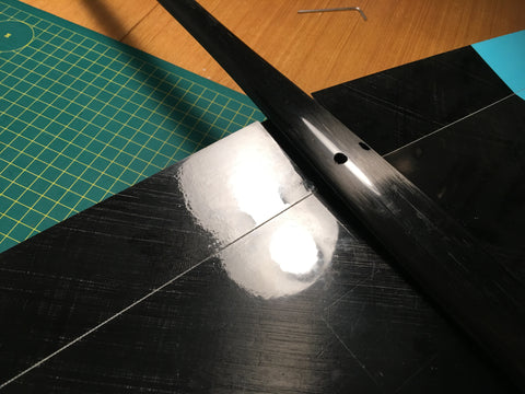
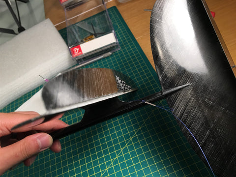
7. Apply a piece of masking tape to the left wingtip. Mark the shape of the throwing blade tang, and cut off a small piece of the tip where the blade will be inserted.

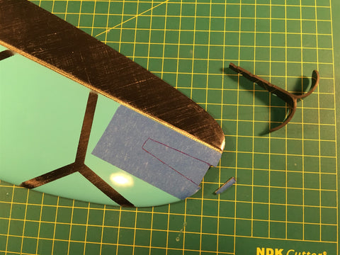
8. Mark the drill bit with a piece of masking tape on the depth of the tang, so that you do not remove too much foam by accident.

9. Using the drill bit, drill through the foam along the two edges of the tang, and then proceed to remove the foam in between. This way you will have a nice tight fit without lots of empty volume that needs to be later filled with epoxy, helping ensure a light and strong fit.


10. Scuff up the throwing blade and wipe clean with rubbing alcohol. Optional: you can also use a file to sand the tang so that it tapers towards the trailing edge for a nicer installation. Mix some 15-minute epoxy and mix with a little bit of microballoons and aerosil to lightly thicken the mixture (don't thicken it to much!). Apply the epoxy mixture into the cavity and on the throwing blade tang, make sure you apply enough so that some excess epoxy comes out when you push in the tang to avoid any air pockets. Use a piece of soft foam or kitchen foam to pad the wing, and clamp down with a little bit of pressure to ensure a good direct bond between the skins and throwing blade.
*Note, make sure the throwing blade is installed the correct orientation, with indentations along the trailing edge and with the bottom part of the blade offset into the wing relative to the top part.


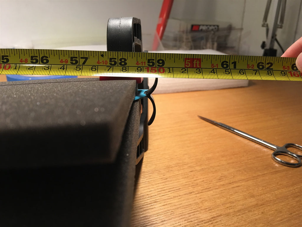
11. Make sure the installed blade is within the 1.5 meter wingspan limit. Adjust quickly before the epoxy cures if needed.
Fuselage
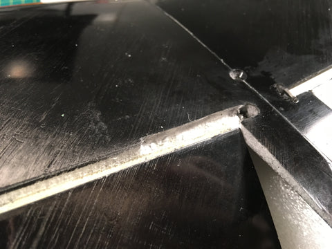
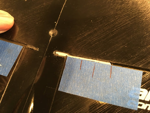
1. Apply a piece of masking tape on the wing saddle where the control horn from the wing passes through. Mark the place and make to small drill holes. Widen carefully with a round file while checking by placing the wing onto the fuselage to ensure the hole is as small as necessary while allowing full unrestricted movement of the control horn/flaperons.


2. Apply a piece of masking tape on the bottom of the fuselage, and mark two holes directly below the two holes cut into the wing saddle in stop one. Drill, and enlarge slightly as necessary. It's recommended to enlarge towards the center of the fuselage as the two sides need to keep integrity to oppose launch loads.
*Note: Make sure your holes have rounded corners.
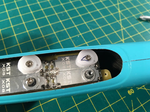
3. Trial fit the four servos onto the servo tray. Remove two of the servos from one of the sides. Sand and clean the servo tray edges and the inside of the fuselage, and insert the servo tray (with the two servos). The servos will give you a depth gauge so that you can install the tray as deep as possible while allowing for room enough for the servos. Position the servo tray so that the hole for ballast at the rear of the tray is closer to the bottom of the fuselage, and immediately in front of the rear of the canopy opening. Drip a few drops of superthin CA along the servo tray/fuselage joint, and apply a little bit of kicker to speed up the curing process. Remove servos, and apply the CA along both joints. Let cure and apply again, until there is a small fillet of glue at the joint. Spraying with a little bit of kicker between applications will speed up the process. Reinstall servos.
*Note: The openings for the servos is slightly offset so that the servo horns (or pulleys) for the tails is on top, and the servo arms for the wings is on the bottom.

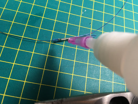
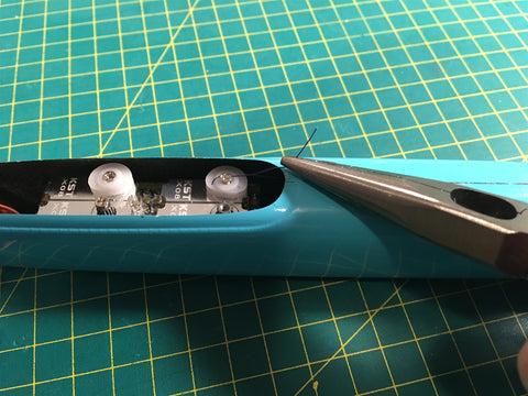
4. Take the two carbon tubes and mark out their appropriate lengths. The rear servo should move the left flaperon (viewing the plane from the top surface, with the nose pointing up), and the forward servo should move the right flaperon. Bend two L shapes in the supplied pushrod material, rough up the pushrod and clean with rubbing alcohol. Wrap the pushrod with the supplied thread as pictured, and hit it with superthin CA and kicker to make it rock solid.


5. Insert the pushrod into the carbon tube, and wick in lots of superthin CA. Apply kicker to quickly cure the CA. Cut a small piece of wire and glue it to the end as pictured, and apply thread with CA to hold the retainer in place. This will stop the pushrod from coming loose from the control horn by accident.


6. Make two more metal pushrods for the front, leaving a bit extra pushrod length so that you have more room for error. Wrap as in step 5, and insert it into the carbon tube. Do NOT glue in place yet. Install it onto the servo arms as pictured. For the front servo pushrod, you may want to bend it a SMALL amount to clear the rear servo, depending on your installation. Do not bend too much otherwise it will not be stiff enough.

7. Install the servo arms and pushrods into the fuselage. Apply superthin CA to the servo arm/pushrod joint and hit with kicker. This creates a bushing and eliminates any slop, as well as providing a retainer that keeps the pushrod on the servo arm. Make sure the servos are plugged into the receiver (with everything set to 0). Install the wing to the fuselage and hook up the pushrod to the flaperon control horns. Shim the flaperons downwards with a small piece of 1/8" (or 3.5mm, whichever is handier) balsa, and tape firm. Apply superthin CA to the pushrod/carbon tube near the servos to finish the pushrod assembly.

8. Using a Dremel, sand and drill the rear of the horizontal tail mount to accept the elevator control horn.


TAILS
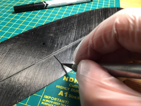
1. Mark the center line of the elevator on the side with the hinge gap as shown. Cut through the top skin and foam core with a hobby knife, but don't cut through the bottom skin. The length of the cut should be the same as the length of the control horn. Using a small file, increase the width of the slot until it firmly accepts the control horn. Sand and clean the control horn, insert it into the slot, but do not glue it yet.


2. Bolt the horizontal stabilizer onto the tail mount on the fuselage. Move the elevator around to make sure the control horn is moving without restriction. Glue with superthin CA.

3. The vertical stabilizer comes in several options. The standard part that comes with the kits is an offset tail with more area on the bottom of the vertical. This is only for right-handed pilots. We also have a symmetrical planform version that works for both left and right-handed pilots. In any option, the following is the same: Mark the the rudder with a line that goes through the boom attachment (that is where the line will come out) on the side with the hinge gap. Cut as with the horizontal stabilizer, and glue with superthin CA.

4. Drill a hole on the side of the vertical with the control horn as pictured. Sand the boom and clean with rubbing alcohol. Attach the wings and horizontal tail, and attach the vertical stabilizer. Make sure it is fitted snugly and perpendicular to the wing and horizontal stabilizer, and wick in superthin CA to glue. Optional: You can also use straight 15-minute epoxy in this joint to make it easier to align.


5. Use the spring stock and make two springs for the tails. Each end leg should be around 15mm long, and the center torsion leg should be about 40mm long. Bend your tail 180 degrees, poke two holes and insert them. Use superthin CA to strengthen the surrounding foam and to lock the springs in place.


6. First we'll do the pull-string installation for the elevator. Pass the wire through the crimp as pictured, ensure that the loop is enough for you to get it onto/off the control horn, and that the line at the end is long enough for you to grab from the outside if your loop drops into the fuselage. Crimp down hard with a pair of pliers and secure it with a drop of superthin CA.


7. Plug in your servos and ensure all settings are at 0. Pass the line through the fuselage with the loop connected to the control horn. In our installation we will be using an Armsoar pulley, but you can also use a standard servo arm for these instructions and model. Pass the line through the far hole in the pulley as pictured, and install the pulley onto the servo. Screw on the servo-arm screw halfway. Pull the line so that the elevator is about neutral, and wrap the wire around the screw several times as pictured. Slowly tighten the screw, making sure the line is secure and the elevator is slightly offset to the downward position by ~2-3mm. You can redo this a few times but take care to not put a bend into the wire repeatedly, otherwise it may fatigue.


8. The pull-string installation on the vertical is essentially identical, with the only two differences being that you do not need the extra length of wire at the end since it will not fall into the fuselage, and that the rudder should not be offset in either direction.

Setup
The recommended CG range for the Vibe 2 is 63-70mm measured from the leading edge of the wing at the root. typically, a CG of around 65mm is used.
Camber settings:
- Launch preset: Flush
- Zoom: 2mm up
- Speed: 1mm up - flush
- Cruise: 2mm down
- Float: 4mm down
- Float2: 6mm down
Make sure you check all the deflection directions before your first flight, have a fully charged battery pack, good luck, and HAVE FUN!
The Vibe2 needs less elevator and rudder deflection than other gliders, so make sure before you test your model you don't have too much deflection otherwise you will overdo it.