
Pull-String Tail Linkage On DLGs
Pull-String Tail Linkage On DLGs
What are pull-string tail linkages?
If you're new to discus launch gliders (DLGs), then pull-string tail linkages might be something new for you, even if you may have been flying other types of radio control planes in the past.
DLGs use several common types of tail linkages, such as pushrods, pull-pull systems, and pull-string installs, and pull-string installs are by far the most popular on a modern DLG.
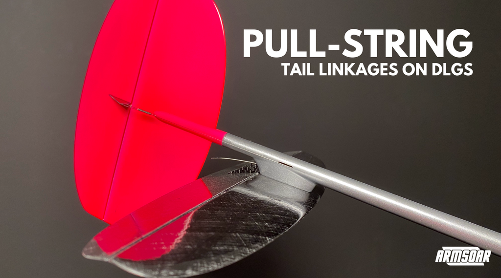
The pull-string installation consists of a torsion spring mounted on the tail that deflects the control surface in one direction, while a string pulls against the spring to hold the control surface in position.
What makes a good tail linkage?
Every type of tail linkage will have its pros and cons, but to determine why pull-string is so popular, we need to understand what makes a good tail linkage design. There are many considerations, but the most important characteristics are that it must be light and accurate.
On any radio control glider, the mass at the extremities like the wingtips and tail must be kept as light as possible to keep the glider agile and to indicate the air it flies through. But on a DLG, this is even more important because of the launch. Heavier extremities mean higher rotational inertia that the vertical tail must overcome to fly straight after the spin going into the launch. The heavier the extremities, the higher the rotational inertia, the more energy is wasted in damping, and the lower the DLG will launch.
Additionally, DLGs are high-performance gliders, and even a little bit of inaccuracy in the rudder or elevator will lead to inconsistent setups. There are three leading causes for inaccuracy:
- Slop in the linkage system allows the control surface to move when the servo is still. Slop can come from loose geartrain in the servo, poor fitment between the pushrod and servo arm or control horn, and soft pushrods that bend along its length.
- Friction in the linkage system prevents the control surface from centring accurately. Excessive friction usually comes from the linkage rubbing against the fuselage openings.
- Low-performance servos will lead to double centring. Double centring from servos can come from slop, as mentioned above, or from low-quality sensors, low build quality, and low torque. Use good servos in your DLGs: KST X06 v6, KST A08 v6.
Types of tail linkage designs
There are three main types of linkages throughout the years for tails on a DLG:
- Pushrods were used for tails and wing control surfaces and are the standard linkage system for most radio control planes worldwide. A well-installed tail pushrod on a DLG is typically a carbon rod or stainless steel wire running inside a perfectly sized and matched etched-Teflon tube. The etched-Teflon tubing is glued inside the entire length of the tail boom for support.
The main benefit of a sound pushrod installation is a solid and reliable linkage that holds the control surface steady in both directions. Pushrod installs also have lower wear and tear on the hinge line.
However, etched-Teflon tubing is hard to source; the installation process is more challenging, leading to slop buildup; and the system is more susceptible to trim changes due to thermal expansion if using a metal pushrod. But the killer - it is very heavy. A pushrod installation will typically add 2-3 grams to the rear of the DLG, increasing the all-up weight by eight grams or more, most of which is at the extremities. This increase in mass has a noticeably poor effect on the glider's handling and performance. - Pull-pull systems were used on several commercially-available DLGs, such as the Concept Xtreme 2/3/4 by Rowing. There are two types of pull-pull linkages: the first method has two strings that connect the two servo arms to the two control horns on the tail surface.
This setup means one string is always in tension to hold the position of the control surface, allowing for similar positive control in both directions like a pushrod install, but at a lighter weight.
However, it is even more challenging to have a properly centring setup with this type of pull-pull design as both strings must be in high and perfectly matched tension and do not remove slop. This tension also leads to accelerated wear and tear on the tail linkages, reducing the centring accuracy.
The second type of pull-pull system incorporates a pulley mechanism near the tail that transfers the pull-pull action to a short pushrod that connects to the tails' control horn.
This design removes the high tension from the hinge line to prevent accelerated wear and tear.
But like the first pull-pull system, it does not remove system slop. And because of the added pulley mechanism, the weight is not significantly lighter than a pushrod setup. - As mentioned above, the pull-string installation consists of a torsion spring mounted on the tail that deflects the control surface in one direction, while a string pulls against the spring to hold the control surface in position.
This system is extremely lightweight, saving eight grams from a pushrod install; the tension eliminates all slop in the linkage and is easy to install well.
Since the control surface is under tension in one direction and actuated by the torsion spring in the opposite direction, spring blowback is possible under very high loads. Power draw is also slightly higher as the servo is always fighting the torsion spring pressure.
Because the pull-string design checks the boxes of being light and accurate while only having minor drawbacks, it has become the defacto tail linkage used on all modern DLGs.
Damping – reduce oscillation
Dampening – make something damp
A on
I thought these set-ups were called Pull-Spring? Derived from the names of other similar systems: Pull-Pull and Push-Pull (aka pushrod)…
Adam (RED) Weston on