GO Mini Assembly Instructions
This manual is not yet complete. You can find a complete build log on RC Groups here starting from post #107. (Updated Oct 29, 2017)
Settings are located at the bottom of the page.
Parts and Materials List
Included Hardware:
Equipment needed to complete the GO Mini assembly:
- 1S LiPo battery pack, 300-400 mAh (300-350 mAh pack if you're using KST X08 v5's for the wings, 400 mAh if you're using EMAX ES9051's for the wings, due to CG balance),
- Small full range receiver with end pins, dual antennas recommended (FrSky X4R, Graupner GR-16L, etc),
- EMAX ES9051 servos (or equivalent) for the tails,
- EMAX ES9051 servos (or equivalent) for the wings on a budget build, or KST X08 v5 servos for the wings on a performance build (recommended).
Supplies and equipment needed to assemble the GO Mini:
- Model knife (X-acto #11, etc),
- Masking tape
- Pen
- Straightedge
- Dremel
- Pliers
- Small file (flat and round)
- Phillips screwdriver
- Epoxy (15 or 30 minutes)
- Microballoons optional
CLICK HERE FOR MY FULL TOOL GUIDE
Wing
1. Using a piece of masking tape, mask the root of the bottom of the flaperon right up against the edge of the flatiron and the hinge line as pictured. Mark the position of the control horn as follows: 1 mm from the edge of the flaperon, and 6 mm from the hinge line.


2. Cut the slot for the control horns using a sharp knife, and use a file to widen the slot to make sure the control horns fit in tight and snug. Roughen the surface of the control horn by scoring it with a knife, and clean the surface with rubbing alcohol to rid it of dust and grease. Glue the control horn into the slots using 15 or 30 minute epoxy. The control horns should be parallel to each other, going straight up with the wing laying flat (control horns should not be perpendicular to the surface of the wing).

3. Use a piece of masking tape to mask the left wingtip (assuming you are a right-handed launcher). Mark the position of the throwing blade, approximately 10-13 mm from the edge of the wingtip, and positioned halfway between the leading and trailing edge of the wing.


4. Using a Dremel with a small drill bit, rough out the hole for the throwing blade. Go slowly, it's much better to remove too little and repeat the action than to remove too much the first time around. Once the opening is roughed out, use a file to finalise the shape of the opening, and to make the edges nice and smooth. Use a knife to pick out the foam surrounding the opening, this will be filled later with epoxy, making a hard point for the throwing blade.


5. Cover the bottom hole with a piece of masking tape. Slit the masking tape lengthwise through the hole, and cover it with another piece of masking tape. This allows you to fill the area with epoxy without any spillage while you work the epoxy into all the crevices to form the hardpoint, and once you peel off the outermost later, the inner layer of masking tape with the slit will allow your throwing blade to pass through.

6. Mix a small batch of 30 minute or 1 hour epoxy, mix thoroughly. Add some microballoons and mix it thoroughly into the epoxy mixture, but don't use too much, it should just be a thick paste that comes off your mixing stick easily by itself. Using a bent piece of wire, work the mixture into the slot and the dug-out areas around the slot, taking time to make sure you work all the air bubbles out so that the mixture fills the area completely.

7. Sand and clean the center of the throwing blade. Remove the outer layer of masking tape from the bottom of the wing, and slip the blade into the wingtip from the top. As the blade nears the center, you may want to add some epoxy onto the center of the blade to make sure you get good epoxy saturation. Wipe off any excess epoxy from the bottom of the blade (where it passes through all the epoxy when you slip it in) and the top of the blade where it joins the wingtip. The bottom surface will have a small fillet once the epoxy cures and you peel away the bottom piece of masking tape. Personally I offset the blade slightly so the bottom half is a little further into the wing, this is to take into account that my middle finger is longer than my index finger for a more balanced and comfortable grip.


Fuselage
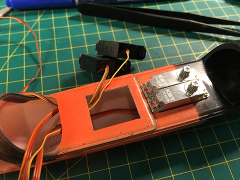
1. Mask the servo tray with masking tape. Mark the centerline (don't worry, it doesn't need to be surgical-precise), and using that as a guide mark the servo sizes. For the economy build, you will be using the EMAX ES9051 on all four surfaces, so it will be 2 servos in front and 2 servos behind. For the advanced/performance build (pictured), your wings will be driven by the KST X08 v5's, which will be installed behind, with the EMAX ES9051's in front. Using a Dremel with a cutoff wheel, or using a drill bit, cut out the two holes for the servos, and file it smooth using a small file. Don't overdo it, you'd rather make the holes a bit small and adjust it slowly so that it fits nice and snug.
Note: Because the wire exits the SIDE of the EMAX ES9051 servos, the holes for the servos need to be about 1mm longer than the actual servo length if installing these servos. Again, please be careful because if you cut it too long then you won't have enough structure to screw the servos in. Patience should be exercised, and the holes should be tested as you go along to make sure the holes don't get made bigger than necessary.

2. Use a small drill bit to drill through the holes in the servo tabs for the screws to make it easier to install the screws, then install the screws for all 4 servos. I recommend using 4 tiny screws to install each KST X08 servo. Plug in the servos two at a time to get them centered, and test the servo arms to see which orientation of the servo arm gives the cleanest (90 degree) installation. Cut off the excess parts of the servo arms. Repeat for all 4 servos.


3. Bolt the wing onto the fuselage, make a note whether the hole on the wing control horn is above or below the parting line on the fuselage side. Take off the wing, and using a Dremel with a small drill bit, drill a small hole on the side of the fuselage as pictured below. Using a small round file you can smooth it out and slightly adjust the shape and location as necessary.

4. Take the wing pushrod wire and bend an L shape on one end, and slip the pushrod into the carbon tube. Position the tube so that the end is 20mm from the L bend, and glue with super thin CA from both ends of the tube. The end with the L bend and 20mm exposed pushrod connects to the wing control horns.


5. Thread the pushrods through the fuselage and out the hole at the side of the fuselage. Hook the L bends to the wing control horns, and bolt the wing on the fuselage.

6. Make two small spacers about 6-7mm high, I usually make this out of scrap balsa. This is used to offset the flaperons while the servos are centred. Offsetting is used on the flaperons because you need very little up deflection, but need a lot of down deflection for brakes.

7. Connect your flaperon servos to either your receiver or a servo tester and make sure they are centred. Mark the hole location on the pushrod with a marker. Remove the wing and pushrods from the fuselage, and bend the wires at the marked spot.


8. Connect the pushrods back onto the servos, and put on a drop of super thin CA as pictured. This makes sure there is absolutely no free play between the pushrod and servo arm, and also creates a keeper so the pushrod does not work itself out of the hole.

9. Using a drill bit, drill two or three holes in the back of the tail pylon on the fuselage. Extend the holes so they form a long opening as pictured.

10. Sand the end of the boom with sandpaper, and clean thoroughly. The vertical stabiliser will be glued to this later.

Tails
1. Using a large drill bit in your Dremel tool, clear out the foam core inside the connector tube on the vertical stabiliser. This tube goes over the end of the boom for an easy and accurate fit.

2. Mask the control surface of both tails where the control horn will go as pictured. Mark out the middle line, then mark out where the control horns will go. The front of the control horn goes directly to the hingeline on the rudder, and is 4mm away from the hingeline on the elevator.

3. Cut along the middle line where the control horn will go using a sharp knife, remove the masking tape, and widen the slot using a fine file. Make sure the horns fit snugly into the slots. Sand control horns and clean with rubbing alcohol, and glue into the slots with 15 minute epoxy.
Note: Make sure the control horn with the open slot is glued to the elevator, and the horn with the closed hole is glued to the rudder.

4. Bend the springs for the tails as shown with the centre section at 40mm long. Both ends are bent pointing the same direction in the same plane, each leg 10-15mm in length.

5. Drill holes for the spring in the tails. The leg that goes in the control surface should be right beside the control horn.

6. Mix some 15 minute epoxy, and deflect the control surface 180 degrees so that the hingeline is fully exposed. Dip the two ends of the spring with epoxy, and insert it into the tail. Use Kapton tape to cover the two ends of the exposed spring, this helps keep the spring inserted tight. Allow the cure before removing the tape and going to the next step.

7. Mount the wing and horizontal tail to the fuselage. Mix some 15 minute epoxy and wipe a little on the end of the fuselage boom where the vertical stabiliser will be mounted. Mount the vertical stabiliser, making sure the control horn is on the side facing away from the throwing blade, and that it is square to the horizontal stabiliser and wing. Allow to cure before going to the next step.

Settings:
These are our latest settings, and may be updated if/when we find something even better.
CG:
- Normal conditions: 68mm
- Turbulent conditions: up to 64mm
Camber:
- Launch Preset: 2mm down
- Zoom: 2mm up
- Speed: 0mm (Flush)
- Cruise: 4.5mm down
- Thermal: 9mm down
Aileron Throws (these are all relative to 0 / root tab):
- Speed: 11.5mm up, 12mm down
- Cruise: 8mm up, 16.5mm down
- Thermal: 4mm up, 20mm down
Rudder Throws:
- All Modes: 10mm left/right
Elevator Throws:
- All Modes: 6.8mm up, 8mm down
- *If your TX programming allows, then the above throws on Zoom mode only, and symmetrical 6.8mm elevator throws on Speed, Cruise, and Thermal flight modes
Aileron-Rudder Mix:
- All Modes: 6mm rudder throw at full aileron deflection
Preset Trim:
- Elevator: 2mm up
- Rudder: 2mm right
Expo:
- All Surfaces: 15%