Vibe Assembly Instructions
More photos to be added soon.
Congratulations on purchasing your Vibe!
Please follow the below assembly guidelines, we have tried to explain each process as clearly as possible through photos and descriptions. In the event that something is unclear, please feel free to send us a message with your questions.
Parts and Materials List
Included Hardware:

- Wing pushrod (2)
- Tail spring wire stock (2)
- Throwing blade (1)
- Tail control horn (2)
- Wing control horn (2)
- Pull string crimps (4)
- Rear wing bolt (1), Tail bolts (2)
- Front wing bolts (2)
- Pull string wire (2)
- Vertical stabilizer connector (1)
- Servo bay covers (2)
- Servo tray (1)
Equipment needed to complete the Vibe assembly:
- 1S LiPo battery pack, 650-900 mah, either cylindrical, or flat and long
- Small full range receiver with end pins (Graupner GR-16L, etc)
- 2 thin servos for the wings, 9mm thickness maximum (KST X08, KST 245S, Graupner DS-427)
- 2 servos for the fuselage, using servos with 8mm thickness will allow them to be installed side by side rather than front and back, saving weight and increasing workable space (KST X08*, KST 245S, Graupner DS-281)
* Stock servo tray is designed for the KST X08 servo
Supplies and equipment needed to assembly the Vibe:
- Model knife (X-acto #11, etc)
- Masking tape
- Pen
- Straightedge
- Thin CA
- Medium CA
- CA kicker / accelerator
- Dremel
- Pliers
- Small file (flat and round)
- Phillips screwdriver
- Hex screwdriver
- Crimping tool optional
- 4-pin connector optional
- Soldering iron and tin optional
- Wire optional
- JR plug optional
CLICK HERE FOR MY FULL TOOL GUIDE
Wing
1. Mask the servo bay area with masking tape and mark the location of the pre-milled top drive tunnel. The tunnel is 50mm from the root of the wing. Then place your servo into the servo bay area and outline the servo for the cutout. Notch the wing so that the servo's ears can slide into the wing. Test fit, but don't glue the servo in yet. Once the servo bay is cut, you will be able to see the pushrod tunnel, and the wiring tunnel.
*Make sure the servo arm is in the root side of the tunnel, and leave a small gap for the pushrod bend.
*Make sure the cutout for the servo and servo ears have a tight fit.


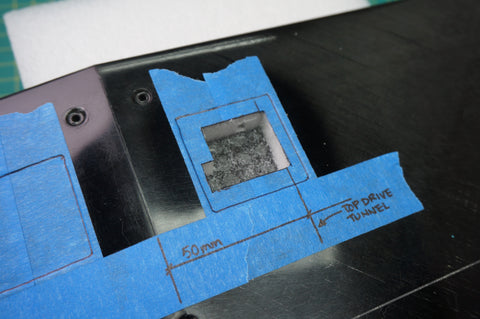


2. Mask the trailing edge of the main wing surface on the topside, and mark the top drive tunnel location. Mark the slot in the wing skin to be cut for the pushrod to come out (start cut 5 mm from the trailing edge, and 10 mm long). Once that is cut, you should see the pre-milled tunnel for the pushrod. Use a long drill bit or stick and run it through the tunnel to ensure it is smooth and clear of any debris.

3. Mask the top of the flaperon and mark the location for the wing control horn. Be sure to leave a small gap (0.2 - 0.5 mm) between the edge of the tunnel cutout and the horn to take the pushrod's bend into account. Cut the flaperon, and test fit the control horn.


4. Mask the bottom of the wing at the root above the wiring tunnel. Bolt on the wing, and draw the outline as accurately as possible. Mark the outline for the wiring to exit the wing. Rather than putting the opening at the root of the wing, I create the opening on the side, right by the wall of the fuselage, on the throwing blade side.* Cut the opening.
*Putting the opening on the throwing blade side has two purposes: a) keeps the fuselage clear for ballast; b) if using an auto-connect installation, the pin and fuselage joint has a much larger surface area for the glue to bond.


5. On the servo arm, drill an appropriate dimension hole right by the hub*. Cut down the servo arm as much as possible to reduce the height. Plug the servos into the receiver to make sure they are at the center, and install the servo arms. Wrap the servos with a layer of masking tape to aid in possible servo removal in the future.
5.a. If not using a 4-pin connector, widen the wiring tunnel and pass the servo wires and plug through, and out the wing opening. Glue in the servos using medium CA or epoxy with microballoons.
5.b. (Pictured) Optional If using a 4-pin connector, cut the servo leads at an appropriate length, and thread it through the tunnel and out the wing opening. Glue in the servos using medium CA or epoxy with microballoons.


6. Optional Prepare the 4-pin connector, and solder the female connector to the wing side. Group the two positives onto one pin, and the two negatives onto one pin, with each signal wire with its own pin*, there is no need for any heat shrink tubing on this side. Cut a length of wire for the fuselage side, and solder the wires to the pin in the corresponding order, and seal with heat-shrink tubing. Crimp JR plugs to the end of the fuselage wire extension to be plugged into the receiver**. Make a mixture of 30 minute epoxy and microballoons, and add enough of the microballons for the mixture to be thick to the point where it is light a wet dough. Wipe it around the exposed wiring on the wing connector, and add some into the wing opening. Plug the connector into the wing, make sure it is straight and vertical, and let cure.
* A good way to make sure you cannot plug it in backwards and fry the servos is to have both electrical wires to one side, and the signal wires to the other side.
** Note you only need 4 wires: 1 positive, 1 negative, and 2 signal wires. Having electrical wiring on the second lead is redundant.


7. Bend one end of the pushrod, and hook it onto the control horn, and slip it into the wing. Use a 3 mm (or 1/8") piece of balsa as a shim and offset the flaperons downwards, tape securely making sure both sides are symmetrical. Use a pen to mark the appropriate bending location on the pushrods. Bend the pushrods outside the wing*, and hook it back into the wing, into the servo and control horn. Turn on the power to the servos, and make sure everything is lined up correctly, and glue the control horns to the wing**. Tape servo covers to cover the servo bays.
*When bending the second bend, consistency between the two sides is key. Remember to account for the length taken up by the bend itself. Have the edge of the plies about 0.5-1 mm on the long side of the mark when bending.
**Whenever gluing anything, remember to first scuff up the contact points, and clean off the dust and grease.


![]()


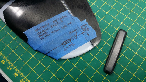
8. Mask the wingtip, and mark the hingeline. Mark a line 90 degrees to the hinge at 20 mm from the tip. The halfway point of this line is the center point of the pre-embedded hardpoint in the wing, and the center of the blade installation. Mark the outline of the blade*, and drill out the meat with a dremel. File carefully with a fine file, test fit with the blade often to ensure snug fit. Scuff then clean the center of the blade, install it**, and glue it with thin CA.
*For better comfort, you may angle the blade slightly by about 1 degree with the leading edge of the blade angled inboard. This will allow better comfort.
**Everyone's blade installation angle is different: some have the blade aligned with the vertical stabilizer, and some tilted one way or another. Personally, I prefer to have the blade at 90 degrees to the bottom surface of the wing panel I am installing it on.

Fuselage
1. Use a Dremel tool and cut out the slot at the back of the horizontal stabilizer pylon. Sand smooth with a fine file.

2. Test fit the servos onto the servo tray. Screw the servos onto the tray while the tray is not yet installed so ensure a perfect alignment. Take off one of the servos, and slip the assembly into the fuselage. Sand the inside of the fuselage where the servo tray will be glued, and clean. Place the servo tray assembly (with the servo) as low as possible, and as far forward as possible while still allowing you to install the noseweight, battery, and receiver in front of the servo tray assembly.Tack the servo tray in place with 4 spots of medium CA in each corner, and spray with CA kicker. Once it cures, remove the servo, and add thin CA along the joint. Kick the CA if necessary, and repeat until a small fillet is formed.
*For added security, wick a small drop of thin CA into each of the eight screw holes for the servos on the servo tray. This will give a much stronger grip for the screws.


3. Mask the wing saddle and carefully mark the wire opening to match with the opening on the wing's side.
3.a. If using servo extensions only, cut a slightly large hole to make sure both plugs on the wings can fit through.
3.b. (Pictured) Optional Mark the opening carefully, and lightly file with a fine file, checking often, to make sure the opening is properly located and sized.


4. Optional Run the wing connector wire under the servo tray, and up through the connector hole. Plug the wire into the wing, make sure it is plugged correctly, and double check by plugging it into the receiver and turning it on. Bolt the wing onto the fuselage. Make a mixture of 30 minute epoxy and microballoons, and add enough of the microballons for the mixture to be thick to the point where it is light a wet dough. Going through the radio gear opening in the fuselage, use a small long stick to apply some of the mixture onto the connector and wires on the fuselage side. Use a flashlight for a better view, and let cure. Take the wing off, and wick some thin CA or medium CA from the wing saddle to ensure a solid bond. Sand smooth the glue if it cures proud of the wing saddle.

5. Install servos back onto the servo tray, and lock in place with the eight screws.
Tails
1. Take the vertical stabilizer connector, and cut it down so that there is 5 - 7 mm on each side, and the back reaches the rear of the spar in the vertical stabilizer so the forces are properly transferred. Drill a hole on the bigger side for the pull string to pass through. Sand all bonding surfaces, clean thoroughly, install, and glue with thin CA.
*The vertical stabilizer and mount are not symmetrical, make sure it is glued correctly.


2. Mark the location of the control horns on the tail surfaces, dead center of the control surfaces. On the vertical stabilizer, ensure the point of where the pull spring pulls is right above the axis of rotation on the hinge. On the horizontal stabilizer, offset it backwards by 1 mm. Remove the small carbon material blocking the channel on the control horn for the horizontal stabilizer, this will allow you to use a hoop on the pull string for attachment. Scuff and clean the control horns, and install them into the control surfaces. Align and double check there is no interference on all travels, and glue with thin CA.
*On the horizontal stabilizer, you can first screw it onto the fuselage, and move the control surface to make sure the control horn does not interfere with the fuselage and pylon before gluing it.


3. Scuff the inside of the connector and the outside of the end of the boom, and clean thoroughly. Install it and align carefully so the vertical stabilizer is 90 degrees to the horizontal stabilizer. Wick in thin CA, repeat until it will no longer wick inside.

4. Bend the spring wire stock, with 10-15 mm legs, and a 40 mm torsion length. Insert one into each tail, and wick in CA so that the legs are properly glued to each control surface inside, and that the foam in the surrounding area is hardened.
5. Cut the servo arms for the fuselage, and use the hole that is 5 mm away from the rotational axis.
6. For the rudder pull string, thread the pull string through the connector. On the tail side, thread a crimping tube over the wire, hoop the wire through the control horn, then thread it back through the crimping tube, and crimp with pliers. Add a drop of thin CA. On the fuselage side, turn on the servos, and thread the crimping tool, thread through the servo horn, and then through the crimping tube again. Make sure the wire is tight and the control surface is as close to neutral as possible, and crimp with pliers. Add a drop of thin CA.
7. For the elevator pull string, thread the pull string through the crimping tube, and then back onto itself, to form a small hoop. Crimp, and add a drop of thin CA. Thread through the elevator pylon, and screw the horizontal stabilizer onto the mount. Hook the string onto the control horn. On the fuselage side, turn on the servos, and thread the crimping tool, thread through the servo horn, and then through the crimping tube again. Make sure the wire is tight and the control surface is as close to neutral as possible, and crimp with pliers. Add a drop of thin CA.
*For ease of assembly at the field, when forming the hoop, leave an extra length of wire through the tube. Fold this 180 degrees and use CA to glue it onto the tube, and allow this length to exit the opening. This will give you something to pull onto in case the wire falls inside the fuselage during assembly at the field.
Setup
The recommended CG range for the Vibe is at 65 mm to 73 mm measured from the leading edge of the wing at the root. Typically, a CG range of 68 mm to 71 mm is used.
Camber Settings:
- Launch preset: Flush
- Zoom: 2 mm up
- Speed: 1 mm up - flush
- Cruise: 2 mm down
- Float: 4 mm down
- Float 2: 6 mm down
Make sure you check all the deflection directions before your first flight, have a fully charged cell, good luck, and HAVE FUN!